
What makes TrueRC antennas different? Mostly the right attention and care for all the key parameters that make antenna performances.
Radiation pattern:
The Gain is a troubling figure, it’s not always the more the better, nor represent the antenna performances in a meaningful way without a map to accompany it. That map that shows how the gain is spread around an antenna is called the radiation pattern.
Here are two simulated patterns of our compact helical singularity antenna, using two different methods of calculation. They both predict a gain of around 1.5dBi that spread energy evenly around a donut-shaped pattern, the usual omni antenna pattern we imagine all being more or less the same.
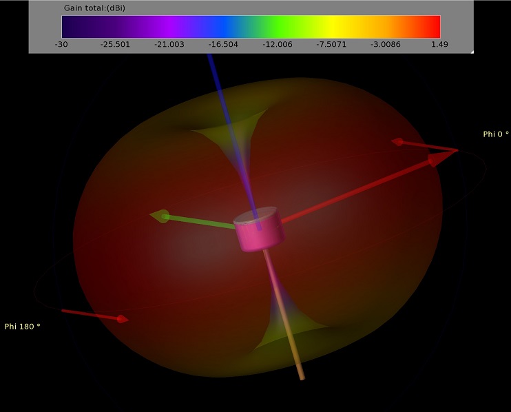
Singularity antenna simulation using finite element method.
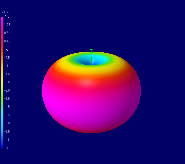
Singularity antenna simulation using method of moment.
What about the reality? Here’s an anechoic chamber test results of the singularity. The predicted pattern matches the results with remarkable accuracy.
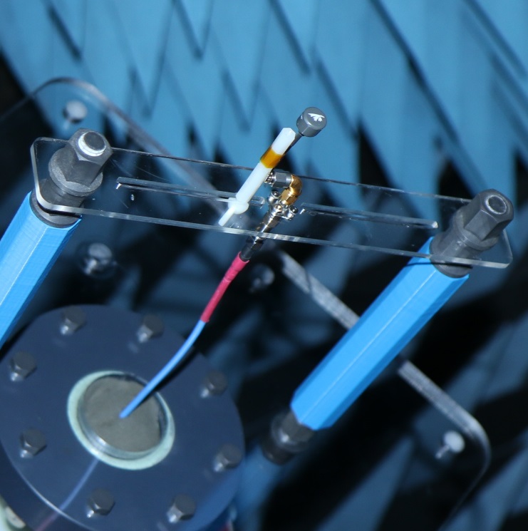
Singularity on the test stand.
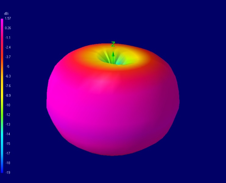
Measured pattern from the singularity antenna in anechoic chamber.
You see the pink area (1-1.57dBi) is evenly spread around the antenna, just like in the simulated results, which helps to ensure a good link in most orientations. For comparison, below is the anechoic chamber test results of an antenna found on many RTF drones and video equipment.
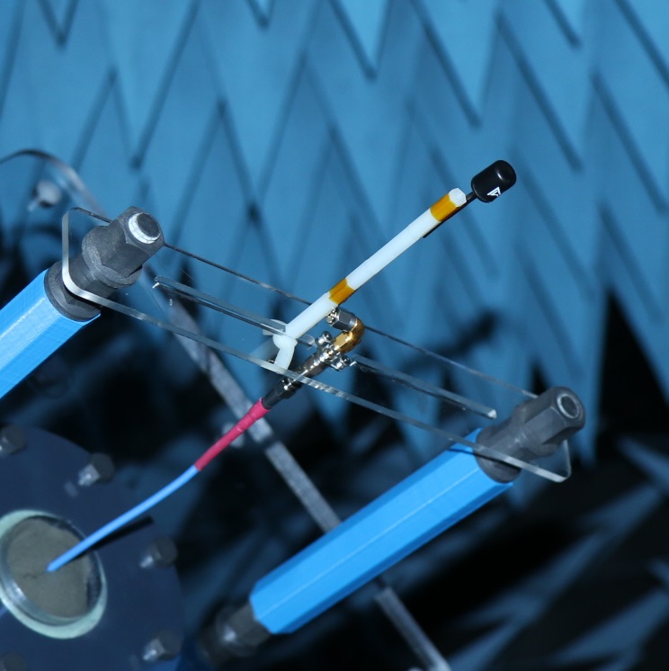
RTF antenna on the test stand.
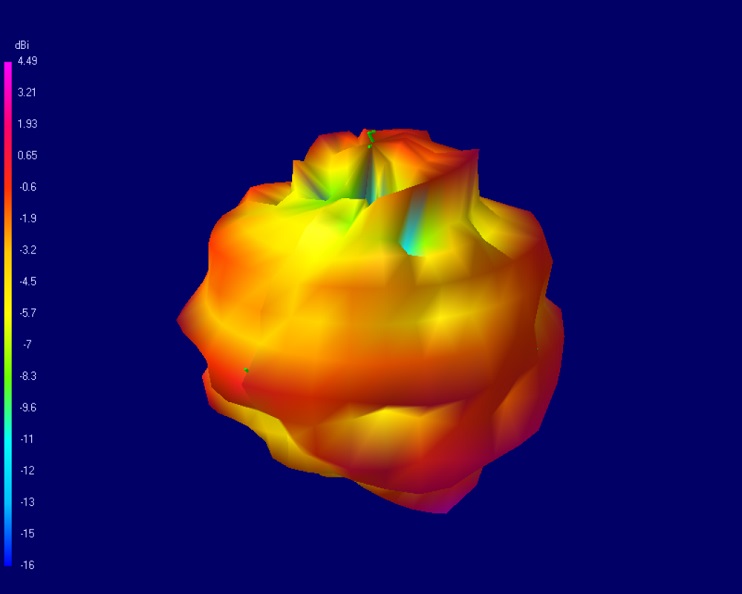
Measured pattern from RTF drone antenna in anechoic chamber.
The gain of this antenna is not evenly spread, the area of highest gain (4.49dBi) is somewhere around the bottom (shown in pink) where it can hardly be useful. The rest form a randomly distributed mountains and valleys that make for unpredictable results. While one could boast a 4.5dBi gain figure for this antenna, its distribution around the antenna makes it useless. It is also probable the distribution will vary from antenna to antenna. For the record, the manufacturer claims 1.9dBi.
Circularity:
Circularly polarized antennas come in two different flavors: Right-Hand Circular Polarized (RHCP) or Left-Hand Circularly Polarized (LHCP). As in real life, nothing is perfect, so an RHCP antenna will always produce some LHCP waves and vice versa. A good metric to look at is the cross polar gain, or for example, how much LHCP waves an RHCP antenna produces. Understandably, we want this value to be as small as possible. Below is the cross polar gain of the singularity as measured by an anechoic test.
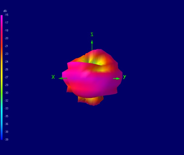
Measured cross polarized pattern from the singularity antenna in anechoic chamber.
You can see the pattern highest point start at -15 dBi so the difference between RHCP and LHCP gain is at least 16.5 dB denoting a very pure circular polarization, in other words, an excellent circularity. In comparison, the RTF antenna measured cross polarized pattern show peaks up to 3.7dBi meaning it isn’t clearly RHCP nor LHCP.
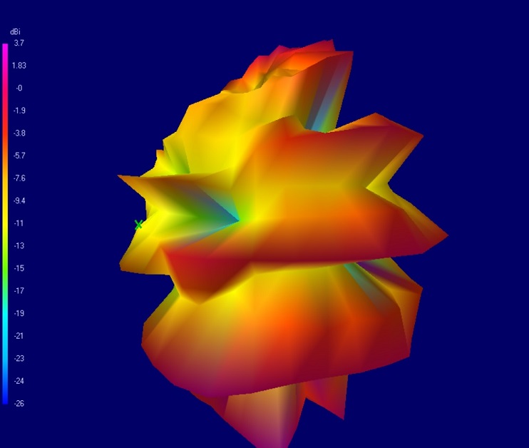
Measured cross polarized pattern from RTF drone antenna in anechoic chamber.
This antenna claims to be circularly polarized, but little circularity can be detected. A regular sleeve dipole would be a better alternative in this case as they have at least an even radiation pattern. Again, the manufacturer claims -15 to -30 dBi cross polar gain, which seems a bit far from our measurements. (Likely a copy paste from our website). These antennas, found on many drones, contribute to the myth that CP antennas have less range than linear antennas. The fact is that they aren’t CP at all, they are just claiming to be.
As you can see, manufacturing a small circular polarized antenna reliably is not easy. Good SWR can be attained, but distributing that RF energy efficiently and evenly while maintaining circularity is another challenge altogether.
We also carefully balance other parameters such as efficiency, SWR and their respective bandwidths.
No Comments