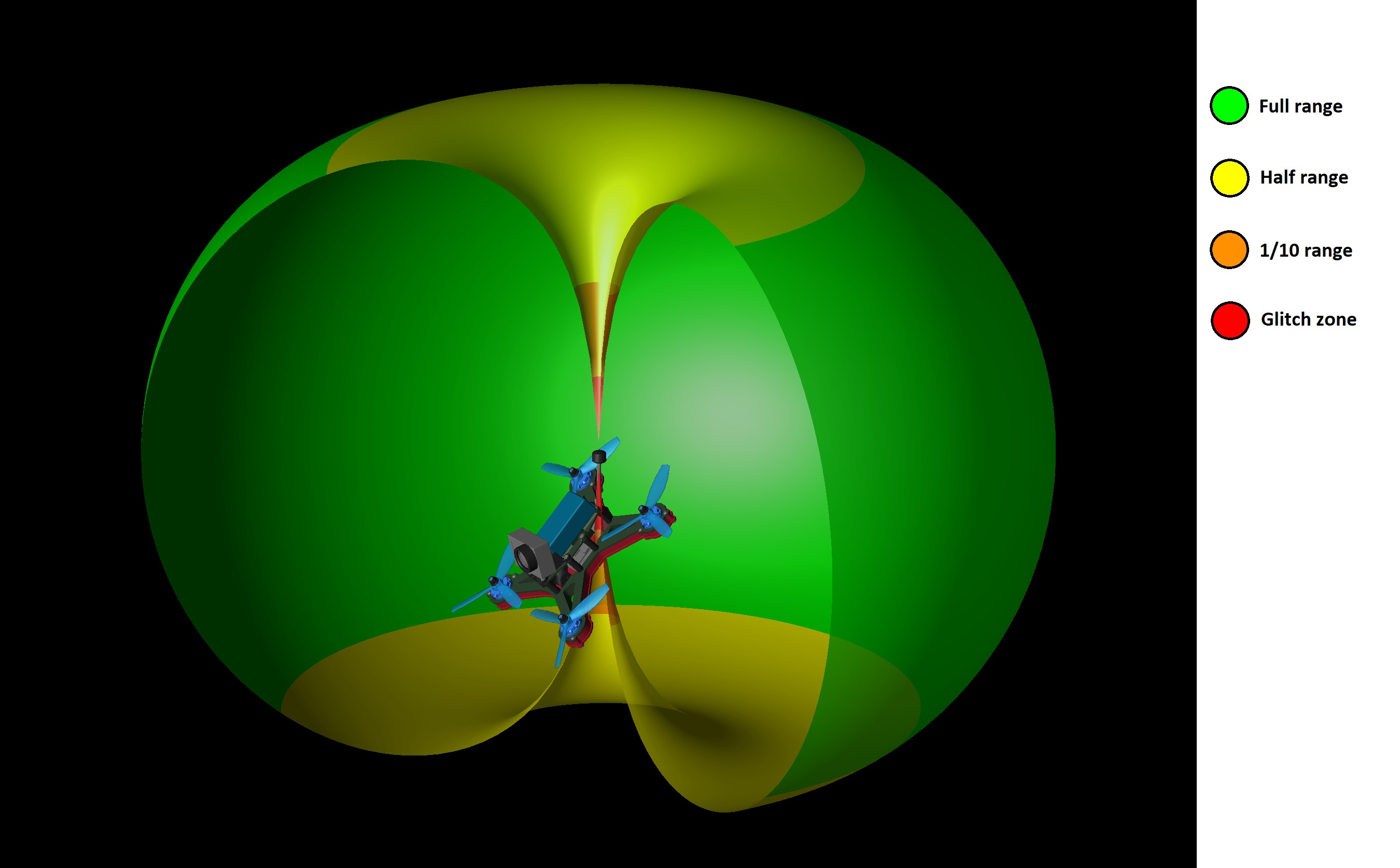
Above is a radiation pattern from an omni directional antenna (AXII) typically found on aircraft transmitter. The usual dBi unit been replaced by ratio of maximum range. You may ask why we didn’t simply marked in meters or kilometers? Because the ultimate range depends on a lots of others factors than one antenna.
However, keeping everything else the same, we can safely assume that when tilting the aircraft enough to put the ground station toward the yellow area, our range is now less than half what it was in the green area. When installing your antenna, it is important to be mindful of the nulls (red and orange) founds directly below and above the antenna. They should point toward the sky and ground when in flight. The quadcopter shown in the picture is a perfect example, with a 45deg tilted antenna so it stay upward when the copter moving forward at 45deg angle. You may have seen people installing their antennas horizontal coming out the back or their quadcopters. While this is not optimal, it still place the green zone within the horizon when in fast flight. If it mean saving your antenna/Vtx from a gate or branch it is a perfectly acceptable compromise. Furthermore, the faster it goes, the better the signal, that certainly doesn’t sound bad 🙂
No Comments