
The pagoda antenna was developed by Maarten Baert as a free to use design. It quickly became a popular antenna, with multiple brands selling them as is or with various attempts to encase or otherwise protect it. In this post we will study the inner functioning of the pagoda and what are the effects of different protection methods.
Below is a rendering of a simulation I made of the pagoda, much like Maarten did.
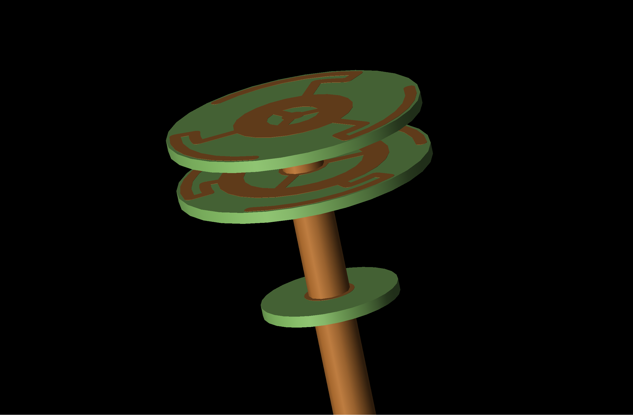
Maarten’s pagoda modelized in 3D EM-sim.
My results matches Maarten’s, Antenna Test Lab’s and my own lab test pretty closely, so I would assume the modeling is correct.
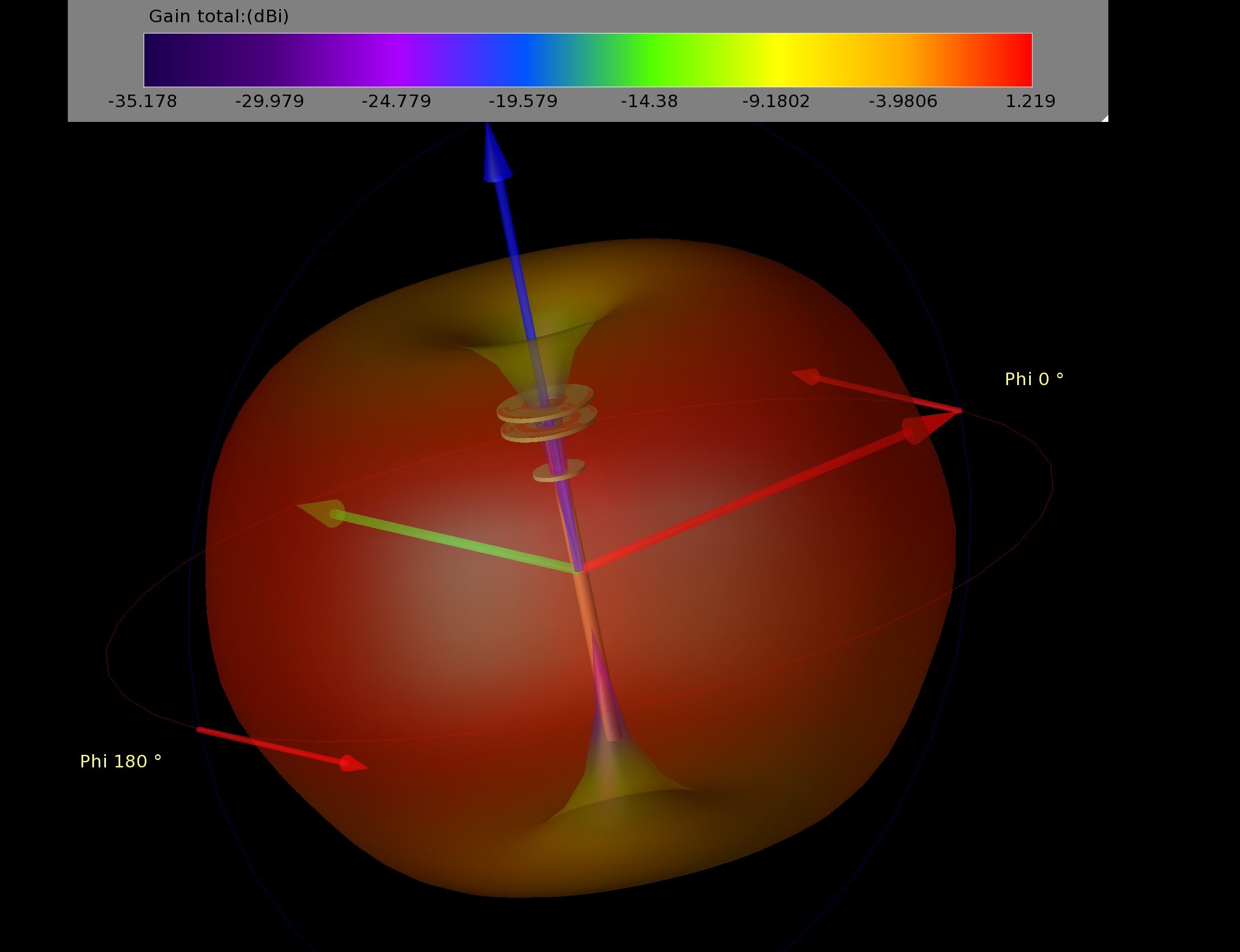
Simulation results.
- Gain: 1.2dBi
- Axial ratio: <2.25dB
- efficiency: 75%
- S11: -22dB
A built pagoda antenna, SWR curves match the simulated model very closely.
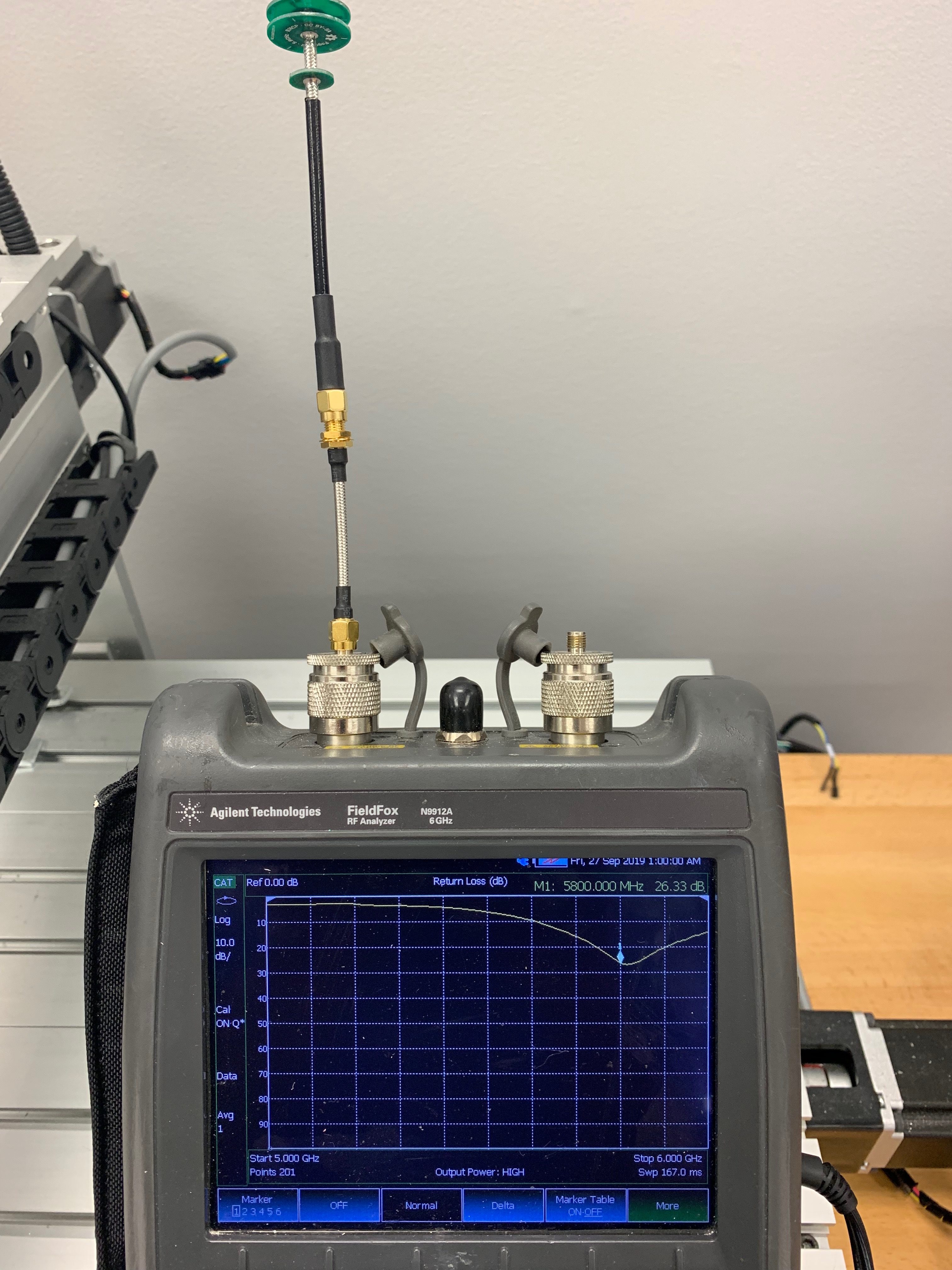
Built pagoda antenna as per Maarten’s design.
Now that I have an accurate model of the antenna, let’s talk about it’s inner working. The pagoda contain 4 individuals antennas; one at the center and 3 placed at the periphery. The center round section act as a vertical radiator, the two circles of copper produce a vertical polarization like a dipole would. The 3 pairs of arced elements act as horizontal radiators. They are 3 dipoles placed horizontal to produce horizontal radiation. The combination of both vertical and horizontal polarized waves produce circular polarization. The third plate prevent a third linear component radiating from the cable.
Placing something between the plates will change the operating frequency of these elements. For example: Filling with hot glue.
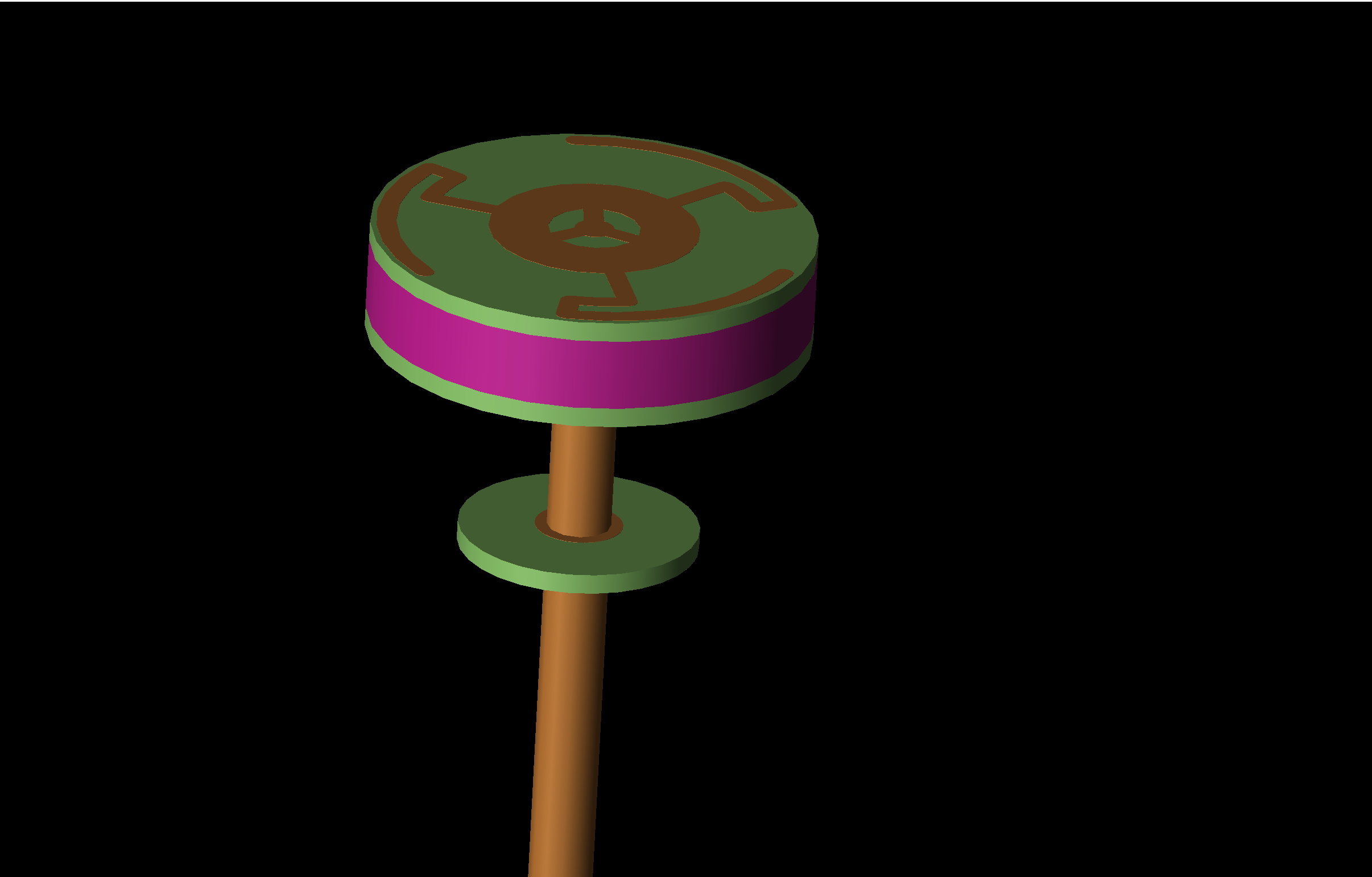
Hot glue modelized in pink.
The pink part represents hot glue. We used ethylene-vinyl acetate, a common component of hot glue and matched the electrical properties of the pink part. The simulation results show a center frequency variation from 5.8GHz to 5.1GHz. The efficiency at 5.8GHz goes down to 38% and axial ratio raise to 4.5dB. In the field, this will translate to a loss up to 65% range because of the compounded effect of reduced efficiency and pattern distortion. Some, flying close in and/or using powerfull Vtx, might not even notice the drastic changes, but the additional heating of their VTx should be concerning.
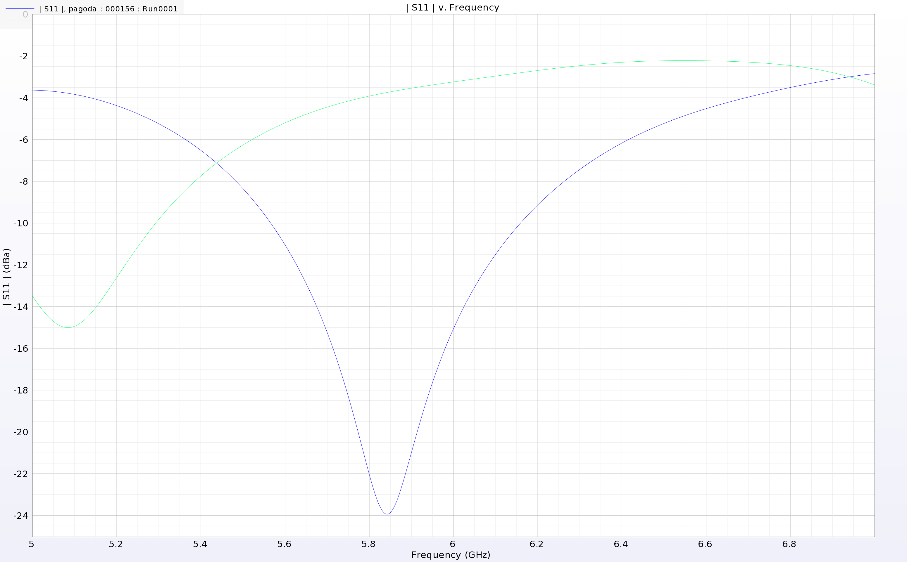
SWR curve with hot glue (green) vs unprotected (blue).
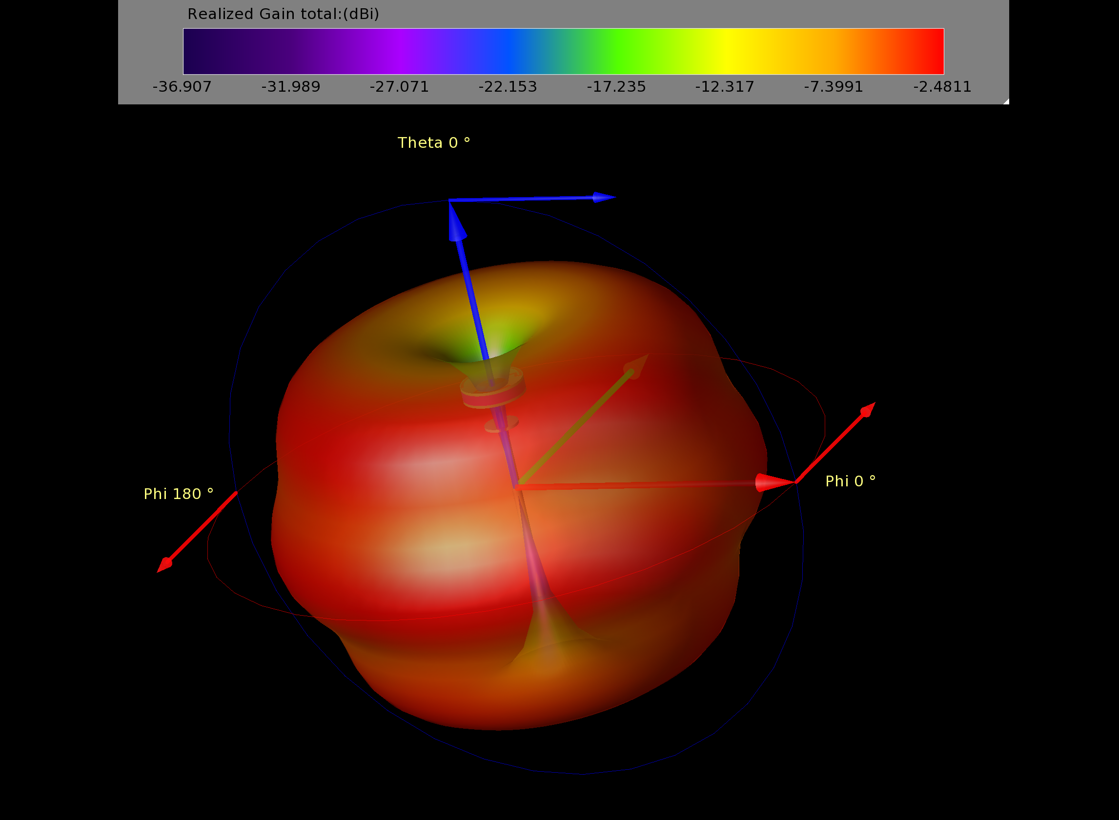
Gain pattern with hot glue
I filled the space between the two top plates of my pagoda with hot glue, the effect on SWR matches the prediction quite well.

Another method is the covering with heat shrink. Below is the heat shrink modelization, I used polyolefin as material properties.

Modelized heatshrink around main elements.
This time the effects are less pronounced. With a loss of efficiency around 15% which is tolerable. Heat shrink won’t protect the pagoda much as the glue does, but in my opinion it is a wiser choice. Some pagoda variations allow for compensation of the effect of covering the antenna, they should give back some of the 15% that was lost initially.
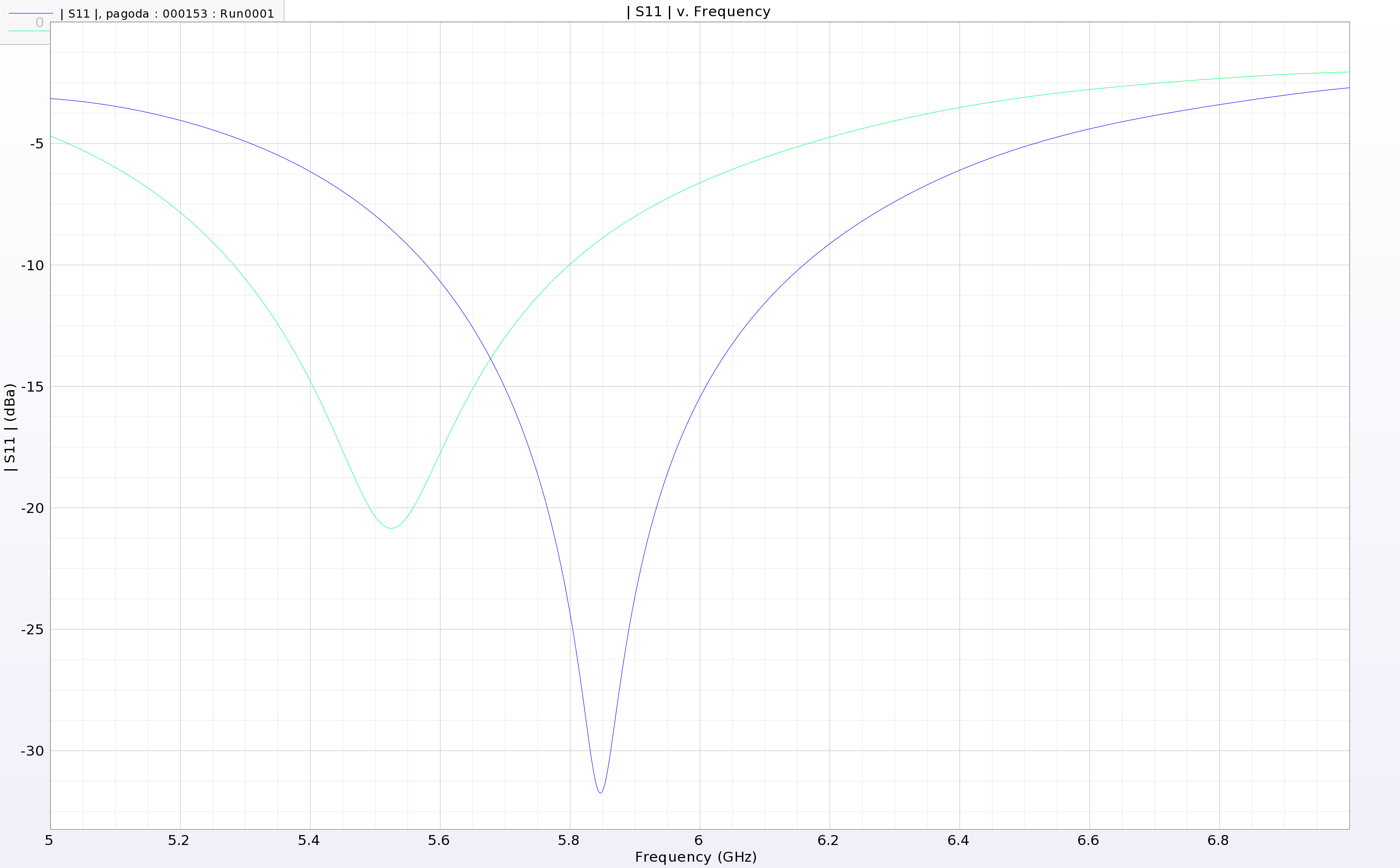
SWR curve with heat shrink (green) vs unprotected (blue).
No Comments